After understanding what pulse electroplating is and its parameters, this second article focuses on the diffusion mass transfer behavior during cathodic electrodeposition. It analyzes the differences in limiting current density and current efficiency between direct current (DC) electroplating and pulse electroplating, which arise from variations in the formation and thickness of the diffusion layer.
Pulse electroplating focuses primarily on the cathode, where electrodeposition occurs. The process mainly involves the mass transfer of metal ions to be deposited toward the cathode, followed by the acceptance of electrons by these ions and their subsequent deposition onto the cathode surface. Generally, these processes occur in series, so the apparent rate of the overall electrodeposition is determined by the slowest individual step, known as the rate-determining process. In typical metal plating, as the current gradually increases, concentration polarization intensifies, and the rate-determining process gradually shifts to the mass transfer of metal ions.
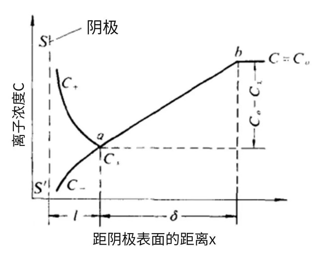
Figure 3-1 Ion Concentration Variation near the Cathode Surface
Figure 3-1 shows the typical ion concentration variation near the cathode surface. For clarity, the electric double layer is illustrated. Here, L denotes the electric double layer. Within the electric double layer, hydrated metal cations are highly concentrated due to attraction by the negative charge on the cathode surface, while anions are repelled by the same charge and thus present at a lower concentration. As a result, cation and anion concentrations are unequal inside the double layer, with cations being dominant.
Beyond the electric double layer lies the diffusion layer, which is generally a laminar layer. The electrolyte here is electrically neutral, so cation and anion concentrations are equal. Within the diffusion layer, the diffusion rate of metal cations follows the diffusion law, and the diffusion rate is determined by the concentration gradient.
Mass transfer includes diffusion, electromigration, and convection. Near the electrode surface, the liquid is generally laminar due to the influence of electrolyte viscosity and electrode roughness, so the effect of convection can be neglected. Furthermore, in practical electroplating, the addition of sufficient supporting electrolyte renders electromigration negligible. Therefore, only diffusive mass transfer is discussed in this paper.
In direct current (DC) electroplating, the variation in metal cation concentration at the cathode surface follows the pattern described in the figure above. During electroplating, the diffusion layer gradually thickens until it reaches the turbulent interface, at which point it enters steady-state diffusion with a thickness denoted as δ. When the cathodic deposition rate is diffusion-controlled, the cathodic current follows the relationship described by the formula:
i = n × F × A × D × (C₀ - Cₛ)/δ
where D is the diffusion coefficient of the metal cations at the given temperature, C₀ is the bulk concentration of metal cations in the electrolyte, Cₛ is the concentration of metal cations at the cathode surface. Under steady-state diffusion (i.e., δ reaches a constant value), if the metal cation concentration at the cathode surface drops to zero, the diffusion rate of metal cations reaches its maximum, and the current becomes the cathodic limiting current, denoted as iL.
If the electrolyte is stagnant, the diffusion layer will continue to thicken, causing a decrease in the limiting current and impairing electroplating efficiency. For instance, in copper electroplating, stagnant electrolyte leads to lower current efficiency; therefore, it is necessary to enhance convection by implementing electrolyte circulation in the plating bath.
Different from direct current electroplating, in pulse electroplating, we use the double diffusion layer model to interpret the variation of metal ion concentration near the cathode.
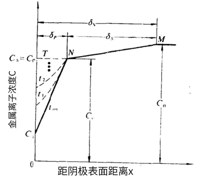
Figure 3-2 Variation of Metal Cation Concentration at the Cathode Surface in Pulse Electroplating
In the double diffusion layer model of pulse electroplating, there exist the pulse diffusion layer δₚ and the steady-state diffusion layer δₛ.
During the cathodic polarization (Tₒₙ period), the concentration of metal cations at the cathode surface decreases. Since the polarization time is short, the inner diffusion layer develops slowly and remains thin; this inner layer is denoted as δₚ.
The development of the pulse diffusion layer lowers the metal cation concentration at the outer boundary, establishing a second concentration gradient, which further forms the steady-state diffusion layer δₛ.
During the Toff period, driven by the concentration gradient, the metal cation concentration at the cathode surface recovers, and the degree of recovery depends on the selected pulse parameter Toff.
In reverse pulse electroplating, the cathode acts as an anode during the polarity reversal period, which accelerates the replenishment of the depleted pulse diffusion layer.
The pulse diffusion layer evolves repeatedly with each pulse cycle.
Both the diffusion layer formed in DC electroplating and that in pulse electroplating follow Fick’s laws of diffusion.
Fick’s first law describes the rate of steady-state diffusion:
J=D×∂C/∂x
where D is the diffusion coefficient of the species, representing the diffusion rate under a unit concentration gradient.
Fick’s second law describes the time-dependent concentration change at a spatial location during non-steady-state diffusion:
(∂C(x,t))/∂t=D×(∂² C(x,t))/(∂x² )
With appropriate boundary conditions, solving the differential equation yields the concentration profiles for both DC and pulse plating conditions.
In practical DC electroplating, convection stabilizes the diffusion layer after a certain growth stage.
In pulse electroplating, Tₒₙ is typically on the millisecond (ms) scale or even shorter, resulting in a much thinner diffusion layer δ than that in DC electroplating.
Therefore, the limiting diffusion current ip allowed under pulse plating is significantly higher than the DC limiting current under the same conditions.