The rapid expansion of AI computing power demand has driven the explosive growth of the AI server market, which in turn has boosted the demand for Multilayer PCBs. Circuit board designs are increasingly tending towards high aspect ratios and high hole diameter ratios, posing significant challenges to copper plating processes.
Pulse electroplating, with its advantages of strong throwing power and superior copper plating uniformity, is becoming an important process choice under such general demand trends.
Then, what is pulse electroplating?
What are the differences in the mechanism of action between pulse electroplating and direct current (DC) electroplating?
What technical points need to be noted in the design of insoluble anodes in pulse electroplating?
In this issue of the "Technology Insight" column, we will conduct an in-depth analysis of this key process under the industry upgrading trend from an electrochemical perspective. As the first article in this series, it will introduce what pulse electroplating is and its pulse parameters.

Pulse electroplating is an electrodeposition process that uses a pulse power supply. The pulse power supply is turned on and off at a certain cycle; the pulse waveform usually adopts a square wave, but other waveforms such as sine waves are also used. If a reverse current is applied during the off-period, it is commonly referred to as reverse pulse electroplating.
The coating obtained by pulse electroplating has small grain size, strong throwing power, and can achieve a relatively dense, bright and uniform coating.
In the electroplating process of Multilayer boards, pulse electroplating has shown excellent throwing power.
Taking the square wave as an example, the definition and explanation of pulse parameters are carried out.
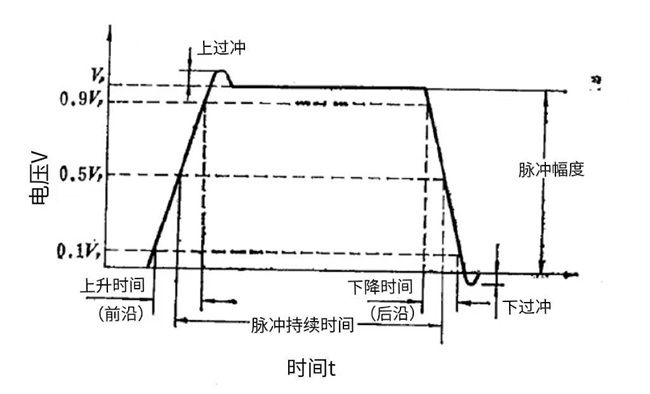
Figure 2-1 Square Wave Pulse Parameters
Rise time is defined as the time required for the voltage or current to rise from one-tenth of the peak value to nine-tenths of the peak value, with a typical rise time of 20-100 μs. Fall time is defined as the time required for the voltage or current to drop from nine-tenths of the peak value to one-tenth of the peak value, with a typical fall time of 30-100 μs.
Pulse duration, commonly known as pulse width (Ton), is defined as the period from five-tenths of the voltage or current rise period to five-tenths of the fall period.
Pulse interval time (Toff) refers to the period when the current is zero or outputs in reverse, which is defined as the period from five-tenths of the fall period to five-tenths of the rise period of the next cycle.
OverShoot and UnderShoot refer to the phenomenon that the voltage or current exceeds the peak value or cuts off at the end during the rising and falling stages. They are mainly caused by factors such as the inductance between the pulse power supply, input and output lines and electrolyte, as well as electrode capacitance.
Pulse period refers to the sum of pulse duration, interval time or commutation time, denoted as

Pulse frequency refers to the number of complete cycles completed by the pulse per second, denoted as
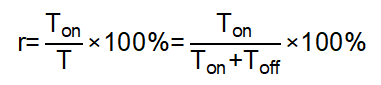
Duty cycle refers to the ratio of pulse duration to the entire pulse period, denoted as
Pulse amplitude refers to the peak value of voltage or current, denoted as Up or Ip
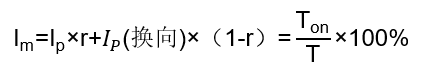
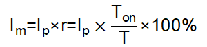
The average current of the pulse is denoted as lm
Since pulses include commutation and non-commutation pulses, the commonly used calculation formulas for the average current of square wave pulses and square wave commutation pulses are listed here. For non-commutation pulses:
For commutation pulses: