In the first and second installments, we have understood the concept of current efficiency and analyzed the factors affecting the current efficiency of electrodes. As the final installment of this series, this article will elaborate on the factors affecting the current efficiency of electrochemical reactors.
The full text is 1,243 characters long, with an estimated reading time of 4 minutes.
1.What is Current Efficiency?
1.1 Faraday's Law
1.2 Electrochemical Equivalent
1.3 Current Efficiency
2.Factors Affecting Electrode Current Efficiency
2.1 Anodic Current Efficiency of Chlor-Alkali Electrolyzers
2.2 Anodic Current Efficiency of Sodium Hypochlorite Production by Electrolysis
2.3 Cathodic Current Efficiency of Metal Electrodeposition from Aqueous Solutions
3.Factors Affecting Current Efficiency of Electrochemical Reactors
3.1 Counter Electrode Side Reactions and Electrolyte Side Reactions
3.2 Design Factors of Electrochemical Reactors
There are more factors affecting the current efficiency of electrochemical reactors, with the main ones including side reactions on the counter electrode, side reactions in the electrolyte, and the design of the electrochemical reactor, etc. Specific elaboration is provided with examples below.
Let us still take the electrolytic production of sodium hypochlorite as an example. Typically, the ruthenium-titanium anodes used in diaphragm-free sodium hypochlorite generators themselves boast a chlorine evolution efficiency of over 90%. However, for actual sodium hypochlorite generators, the available chlorine concentration at the water outlet is limited to below 10 g/L, with no room for further improvement, and the overall current efficiency only stands at 60–70%, a far cry from the anode current efficiency. The primary reason for this lies in the side reactions occurring on the counter electrode. Given the absence of a diaphragm during electrolysis, the production of sodium hypochlorite in the effluent relies on a series of solution reactions and requires hydroxide ions generated at the cathode. Consequently, the electrode gap in such diaphragm-free electrolysis systems is generally kept below 5 mm. The hypochlorite ions produced are reduced at the cathode with high efficiency, and this cathodic reduction thus exerts a significant negative impact on the efficiency of sodium hypochlorite generation. In addition, the decomposition of sodium hypochlorite under high-temperature and light conditions also contributes to the decline in the measured current efficiency. Therefore, even if the reaction current efficiency of the main electrode is relatively high, the presence of unfavorable side reactions on the counter electrode or in the solution can drastically reduce the gas production efficiency of the electrochemical reactor. In the industrial electrochemical production of chlorates under similar reaction conditions, a variety of different methods are employed to maximize current efficiency.
Beyond the counter electrode, the design of the electrochemical reactor also significantly affects the nominal current efficiency of the electrochemical reactor.
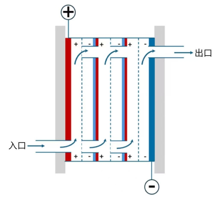
Figure 5 Schematic Diagram of a Typical Bipolar Electrolyzer with Built-in Flow Channels
In the electrolysis industry, bipolar electrolyzers are often a better choice than monopolar electrolyzers in the design of large-scale electrolyzers, owing to their advantage of enabling low current and high voltage operation that facilitates power supply selection. The structure of a typical bipolar electrolyzer is illustrated in Figure 5. Taking alkaline electrolyzers as an example, we discuss the impact of the design factors of bipolar electrolyzers on the nominal current efficiency of electrochemical reactors.
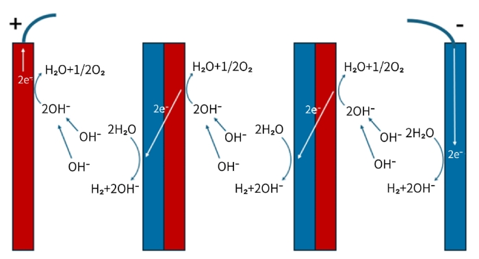
Figure 6 Current Transfer Mode of Bipolar Alkaline Electrolyzers
Figure 6 is a schematic diagram illustrating the current transfer mode of a bipolar alkaline electrolyzer. As can be seen from the diagram, the electric current forms a circuit through three combined pathways: ionic transfer, electrochemical reaction, and metallic electron transfer. For a single bipolar plate, oxygen evolution occurs on its anode side with the release of electrons; these electrons are then transmitted through the metallic bipolar plate to the cathode side, where they are consumed by the hydrogen evolution reaction, thereby achieving charge balance inside the metallic plate. The theoretical calculation of the total hydrogen production assumes that the current density is uniform across all plates, which requires the end plates to effectively transfer electric current to each bipolar plate.
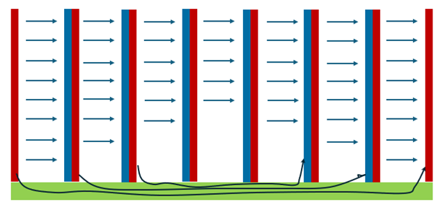
Figure 7 Schematic Diagram of Current Transfer Efficiency of Alkaline Electrolyzers
In reality, however, as illustrated in Figure 7, the common built-in flow channel design of alkaline electrolyzers is equivalent to adding an extra path alongside the main current-carrying path—i.e., introducing a shunt resistor parallel to the main circuit, thus forming a parallel circuit. In a parallel circuit, the current distribution between the two branches depends on their respective resistances; consequently, the built-in flow channels are bound to draw a portion of the total current. This results in the actual current received by each bipolar plate being less than that supplied by the end plates, with a certain reduction factor applied. Moreover, the current diminishes progressively toward the middle of the electrolyzer stack. For this reason, an excessively large number of bipolar plates often leads to relatively low current efficiency.
Similarly, electrodialysis stacks equipped with built-in flow channels suffer from the same issue, which restricts their apparent current efficiency to only 60–70%. In light of this, chlor-alkali electrolyzers generally adopt an external flow channel configuration and employ various methods to minimize the impact of shunt current.
In summary, the decrease in the apparent current efficiency of such bipolar electrolyzers is essentially not directly related to the electrodes themselves but is mainly attributable to design factors.
Our R&D team is dedicated to the development of high-performance anodes and boasts exceptional innovative R&D strength. Leveraging the synergistic advantages of three global R&D centers, we realize cross-regional innovation sharing.
Equipped with advanced and comprehensive R&D facilities, our centers feature high-precision measurement and analysis capabilities, ensuring efficiency and accuracy throughout the anode R&D process.
Global Research Network
With three R&D centers strategically located in Sweden, the Netherlands and China, we maintain close collaboration and share core R&D achievements on a global scale.
Senior R&D Team
Among our R&D staff, 50% hold doctoral degrees and 14% hold master’s degrees, forming a highly educated and professional team.
Patented Innovation
We have been granted a number of cutting-edge patents, establishing a leading position in the R&D of anode products and their applications.
Specialized Expertise
All team members have profound R&D backgrounds in the field of electrochemical electrodes, which guarantees in-depth technical competency and professionalism.
Market-Driven Solutions
We closely align with market dynamics and customer needs to provide customized product solutions.